

Rail Sweeping White Paper
Rail sweeping is one of the most powerful mechanism for construction freeform shapes. Rail sweeping us utilized heavily in many industrial design applications where the visual quality of the object is of high importance. Before we get into some examples and a more detailed discussion lets first define some terms that will help us to explain sweeping and how we have implemented it.
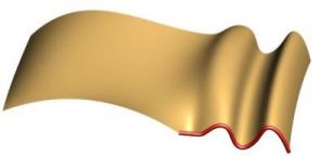
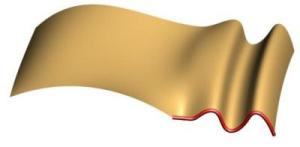
Shape - profile which is to be moved along during sweeping process.
Rail - fixed curve which defines that path along which the shape is to be moved.
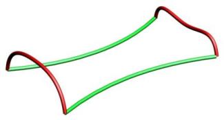
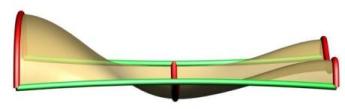
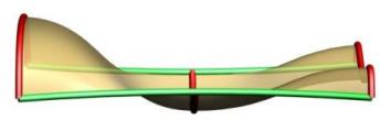
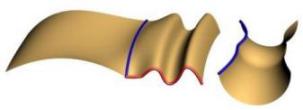
This image shows two shapes (red curves) and the two rails (green curves) the shapes will be driven by .
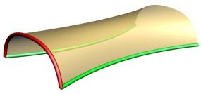
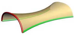
Rail Rotation - the process of rotating the shape to maintain a constant angle with the rail as it moves along the rail.
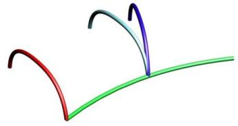
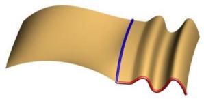
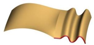
The top image shows the red shape being moved (cyan curve) to a point along the green rail and then being rotated relative to the change in the tangent of the rail to produce the blue curve. The bottom image shows a sweep without and one with rail rotation applied.
Rail Rotation Axis - it is possible to specify an axis to constrain the rail rotations to the specified axis. Typically the Rail Rotation Axis will be one of the major 3 axes (X Axis, Y Axis or Z Axis).
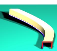
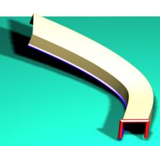
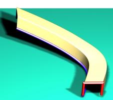
These images show a square shape being swept along a 3-D curve that spirals up like a staircase. We have placed it on a box with shadows so you can better visualize the shape. The upper left image shows the sweep with no rotation. Notice how thin the cross section gets near the end. The upper right image shows the sweep with the default rail rotation where the profile stays at the same angle to the axis. The lower image shows the sweep with a constraint on the rotation to allow it to rotate only around the Z axis (upward vector).
Shape Scaling - as the curve moves along two rails it must be scaled to keep the ends on both rails.
Shape Averaging - if the is more than one shape the shapes must be combined somehow to determine the desired curve the surface will interpolate between the shapes.
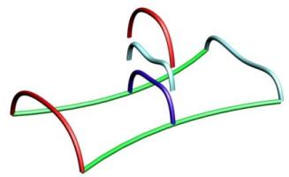
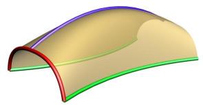
This image shows how the original shapes have been scaled down to fit at the middle of the rails using the shape scaling. The blue curve shows the shape averaging of the scaled Red and Cyan curve.
These three images show three different Shape Scaling techniques we use. First is streatching where we basically streach or shrink along the vector between the rails. Second is uniform scaling where the entire curve is scaled uniformly. Third utilizes a third rail to define the scaling height in direction purpendicular to the line between the two rails.
Shape Blending - for cases where there is more than one shape, shape blending determines how we weight each curve each time we do a shape averaging.
The top image above shows linear shape blending. The middle image shows quadric shape blending. The bottom image shows cubic blending between the curves.
Shape Morphing - the process of modifiying one or more control points of the shape curve to conform to a boundary constraing along one of the rails. The boundary constraints currently supported include: "Tangent Plane", "G1", "C1", "G2" and "C2" continuity. G3 may be supported also in the near future. Our software offers full control over the number of control points allowed in the morphing and the realtive scaling of the morphing. This gives you tremendous flexibility to design very nicely shaped surfaces. These options are typically used when there is an adjacent surface where you wish to blend or if you have a curve with specific shape constraints.
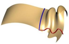
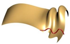
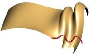
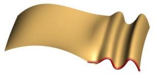
In the upper left and upper right you can see the original sweep without shape morphing. The two lower images show all of the control points of the sweep curve being morphed using the tangent plane constraint. It basically rotates the curve such that the tangent of the start of the shape moves directly down to the tangent plane of the surface at that point.
We can also constrain the locality and strength of the C1 Continuity morphing. In the upper left hand image we morph using just one control point of the shape. In the upper right we utilize two control points in the morphing. By morphing 2 control points we extend out the effect of the morphing into the surface by applying the same transformation to subsequent points. This may have a somewhat undesirable effect so we also have a Morph Falloff flag which decreases the effect of the morph gradually as we move out. For example the lower left image uses falloff and to morph the 2nd control point (actually the 3rd control point in the shape) with only around 1/2 of the rotation of the first. G1 Continuity keeps the length of the curve tangent the same. The C1 Continuity enables you to change the strength of the tangent to either match the tangent field length or some scale factor of it. In the lower right image we morph the first control point put apply a 0.5 scale factor to the morph.
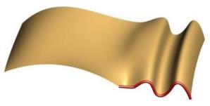
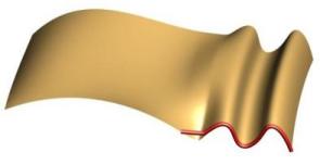
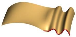
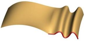
G2/C2 Continuity is required to create "Class A" surfaces. The higher order continuity produces a much smoother looking transition where the radius of curvature matches along the boundary between the surfaces. The upper left is the default C2 continuity where 2 points are morphed (one to achieve C1 and a second to make it C2). The lower left shows morphing of 3 control points without falloff. The lower right image shows C2 using 3 points with falloff.
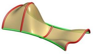
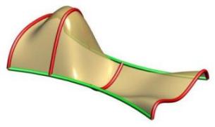
Multiple Shapes are supported with our sweeping tool. Note that the order of the curves is figured out inside of the tool as well as the connection with the rails. The shapes don't have to be right on the rails but will be moved to the closest point to the rail prior to sweeping. Above you can see cases with four shapes with the left one having non-uniform scaling and the right one having uniform scaling. You can see in the left image how the scaling caused by the rail curves causes the surface to go above the 2nd profile.
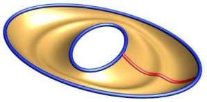
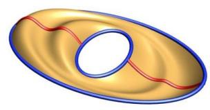
Closed Sweeps are supported and can have one or more profiles. Note that one of the profiles must start and end on the seam(s) of the closed rails. Currently to produce a closed/closed shape like a torus you would need to utilize two sweeping operations.
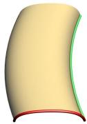
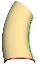
3-Sided Surfaces are supported and work best with uniform scaling. To achieve a 3 sided surface simply bring the ends of the rails together. In the left image you can see how the two blue rails come together. In the right image you can the same effect where the curves come together and are tangent at the zero point producing a nice smooth singularity point like you would see on the top of a sphere.
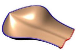
It is also possible to specify continuity along the second rail. Note how the second rail has a fairly large gap with the original profile. The right image shows G0 or just position continuity.
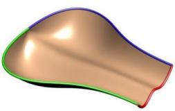
The two images above show C1 Continuity and C2 Continuity respectively on the second rail.
Surface Quality one of the keys to good sweeping is producing a surface which not only looks good but is of good quality in terms of the number of knots and the knot spacing. If you produce a surface that can not be used in down stream applications the sweeping is useless. Surface quality is in part determined by the quality of the curves. If the shapes or the rails have lots of knots you should consider reapproximating them. Our sweeping offers two primary tolerances to control the accuracy of the sweep during the "addaptive" techniques. The first is the 3D distance tolerance and the second is the angular tolerance of the tangency if higher continuity is required.
Five ways to control the creation of the surface and three options on how to utilize the rails shown below:
1) Addaptive Surface Approximation - additional curves are added into the sweep where the tolerance is not satisfied. This is the default and the option that gives the best quality shape with the least number of knots in most cases.
2) Addaptive Approximation with Uniform Knot Spacing -
determines a minimal step along the rail and uses it to produce a set of knots which are equally spaced along the surface rails.
3) Number of Curves - approximates the surface using a given number of curves equally spaced along the rails.
4) At Knots - places intermediate steps at each knot in the rails.
5) At Knots Addaptive - like #4 above except that it utilizes additional tests and may add more curves where need to achieve tolerances.
There are three ways to control how the Rail curves are utilized:
1) Don't use Rails - don't use rail curves in the surface creation.
2) Use Rails - use rail curves as they are passed in
3) Reapproximate Rails - recreates the rail geometry using points and tangents at each of the profile curves.
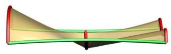
Helix Sweeping is a special kind of rail sweeping where the rail is used as the axis about which to revolve a profile. A second rail can be used to control the relative distance or scale of the profile from the axis. One problem with rail sweeping is that sometimes the surface gets very very long and skinny. This causes problems with some of the mathematics of NURBS and may effect performance. If you have a significant number of revolutions (i.e. more than 20 times around) you might want to consider either doing it in several steps or subdividing the resulting surface into several faces.
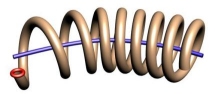
Helix sweeping of a shape around a path.
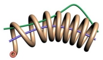
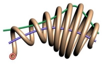
Here we show the before and after when applying a second rail as a scaling curve to control the distance from the axis curve of the shape's path.